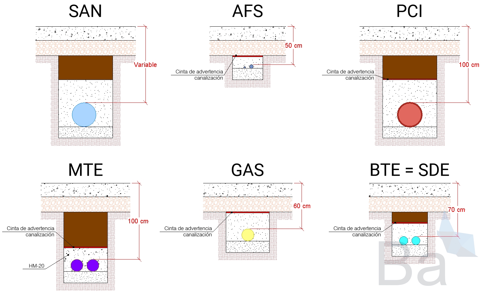
BIM Coordination of Buried Systems in an Internal Urban Development
Author: Pedro Enrique Pérez González
Publication date: February 5, 2024
When coordinating underground utilities within an internal development, many aspects must be considered regarding these utilities, their regulations, materials, diameters, and more.
In this post, we will address all these aspects so that you can take them into account when designing and coordinating utilities with one another.
All the data provided in this post are indicative only and should be considered as a starting point. We recommend that each case be assessed individually and analyzed by a competent professional in the field.
Scope of Work
Before providing any data, it is important to clearly define our scope of work.
Regarding development areas within a project, two main categories can be identified:
External development pipelines
Internal development pipelines
The first group corresponds to the services provided by the local authority to each plot within the municipality where construction is permitted. These typically include water, electricity, internet, wastewater collection, or gas.
The second group corresponds to the pipelines running within the private plot area.
VBB has primarily worked on internal plot developments. Therefore, in this post we will focus on how underground utilities can be arranged to provide the most common services in a building.
Classification of Underground Pipelines
When coordinating underground utilities in a development, the first question we must ask is: what are they conveying?
We therefore establish the following types as a starting point for coordination:
As you may have noticed, each type of installation is associated with an abbreviation that we will use later to provide specific data for each.
Gravity-Driven Systems (SAN)
The most common are stormwater and wastewater systems, although other fluids requiring gravity discharge may also exist, such as industrial process water.
Although pumping may be used in certain sections, it is advisable to classify them within this group because for most of their route they require slope. Therefore, their depth will vary along the entire alignment.
Materials may include PP, PVC, or corrugated PE, with diameters ranging from 110 mm to more than 600 mm.
Water Supply (AFS)
Water supply refers both to domestic cold water systems (AFS) and to filling fire protection tanks or other services requiring running water.
The material is usually HDPE (High-Density Polyethylene), with smaller diameters compared to other installations (25 to 90 mm). This allows greater flexibility to adapt their layout and adjust to other utility routes.
Because they are among the shallowest installations, they are typically the last underground networks to be installed within the development.
Hydrants (PCI)
The requirement for hydrants is established by thea el CTE-DB-SI (depending on built area) and the RSCIEI (depending on built area and the building’s risk classification according to configuration and use).
Where required, the layout will consist of an HDPE network which, in many cases, may involve pipes exceeding 300 mm in diameter, with limited flexibility. Where elbows are needed, they are formed by multiple electrofusion joints, which require specific equipment and significant installation time.
This is one of the most critical installations to protect from potential damage. Although its use may be extremely infrequent, when it is required to operate, it must do so with maximum reliability.
For this reason, when designing utilities in a development, the hydrant network should be assigned a high hierarchy.
Gas
The routes of this network carry what is known as Liquefied Natural Gas (LNG), a type of natural gas that is cooled until it becomes liquid to facilitate transport and storage.
Damage at any point along this network would pose a serious problem, as it could cause gas leakage, which is highly flammable.
Gas can be classified in several ways according to its pressure. Here are some of the most common classifications:
Low-pressure gas: This type of gas is at a pressure equal to or lower than atmospheric pressure. It is used in domestic and commercial applications, such as stoves and water heaters.
Medium-pressure gas: This gas is at a pressure above atmospheric pressure but below 5 bar. It is used in industrial and commercial applications that require a higher gas supply.
High-pressure gas: This gas is at a pressure above 5 bar. It is used in industrial applications that require a high-pressure gas supply, such as welding and metal cutting.
The gas supplied in an industrial building is generally medium-pressure gas.
The materials for this piping can vary, although due to the balance of quality and cost, HDPE (High-Density Polyethylene) is commonly used, with the most common diameters ranging from 40 mm to 90 mm.
Electrical Ducts
The function of this type of conduit is to provide electricity and communications to the building.
This type of installation can be executed with the cable directly buried or in a ducted system. The latter is used to prevent degradation of the cable insulation and to facilitate maintenance. Corrugated polyethylene pipes are used, through which the cables will run from one manhole to another. Diameters usually range from 63 to 100 mm, depending on the number of cables contained.
Although there is a wide variety of cases for this type of conduit, it can initially be summarized into two categories:
Electrical current conduits
Low-voltage signal conduits
If the conduit carries electrical current, it can further be divided according to voltage:
Low voltage (BTE): Voltage up to 1 kV.
Medium voltage (MTE): Voltage from 1 kV up to 36 kV.
High voltage: Voltages above 36 kV.
In this post, we will omit the high-voltage layout, since it is not required in interior urbanizations. Therefore, we will only consider low- and medium-voltage layouts.
Additionally, within low-voltage signals, there are various types, but constructively, their installation and execution within a trench is the same regardless of type.
In Spain, the regulation for these types of conduits is the REBT, specifically section ICT-BT-07, more precisely point 2.1.1, which provides guidance on the depths at which the installation should be executed.
Medium voltage (MTE)
As mentioned, the voltage of this type of conduit ranges from 1 kV to 36 kV, with 20 kV being the most common.
The cross-sections of these cables are also significant, which leads to a larger conduit diameter and, for safety reasons, a greater depth.
The conduit consists of corrugated polyethylene pipes with diameters ranging from 110 mm to 160 mm.
Low voltage (BTE)
These conduits range from 0.6 to 1 kV.
The cable cross-sections are more manageable compared to the MTE line. However, they may also have different diameters.
The conduit consists of corrugated polyethylene pipes ranging from 63 mm to 110 mm in diameter.
Low-current signals (SDE)
These conduits are intended to carry low-current or low-voltage signals, such as those used in telecommunications systems, computer networks, control systems, and audio/video systems.
“Low-current” refers to the sensitivity of these signals, which often require additional protection against electromagnetic interference and other noise sources. This must be considered when executing electrical conduits, as restrictions may apply, for example, when CCTV conduits share a trench with lighting conduits but need to be separated via manholes.
The diameter of these conduits usually does not exceed 63 mm.
Installation depths
Depth is aimed at preventing pipe breakage, which can be caused by several factors:
Freezing of the carried fluid: In very cold environments, the fluid in the conduits may freeze, expand, and break the pipe. This can be mitigated by the insulation provided by the surrounding soil, which increases with depth.
Ground movements: These can occur for multiple reasons, the most common being settlement due to vehicular traffic. Differential settlement can deform the soil and increase stress on the pipe material, causing breakage. In situations where this is frequent or risky, deeper installation reduces the likelihood of damage.
| Installation | Depth | Comments |
| SAN | Variable | Greater length requires greater depth |
| AFS | 50 - 80 cm | Warning tape at 30 cm depth |
| PCI | 100 cm | Recommended |
| GAS | 60 cm | With warning tape 20–30 cm above the pipe |
| MTE | 100 cm | Minimum 80 cm; always with warning tape |
| BTE | 70 cm | If shallower, must be encased in mass concrete |
| SDE | 70 cm | If shallower, must be encased in mass concrete |
For SAN, since it runs by gravity and gains depth along its route, the depth is variable.
For AFS, there is no national technical regulation that specifies the depth at which the installation should be placed. However, there are local regulations that establish a depth between 50 cm and 80 cm, with a blue warning tape at 30 cm depth, such as in the Aguas de Alcázar technical standard.
For PCI, there is also no regulation that governs the depth of this installation, but it should be set at no less than 80 cm, typically between 80 and 100 cm.
When designing the GAS network, we can refer to certain documents from Gas Natural, such as NT-131-E, parte 3³. This document specifies that the depth cannot be less than 60 cm for medium-pressure gas pipelines (MOB ≤ 5 bar).
For the MTE conduit, ITC-BT-07¹ specifies depths ranging from 60 cm on sidewalks to 80 cm on roadways. Since this is a pipe through which a cable runs from one manhole to another, and repairs are rarely required, we prefer to place this conduit at 100 cm from finished grade. Additionally, having this conduit at this depth allows for smoother coordination when crossing other conduits.
For BTE and SDE, we also follow ITC-BT-07¹ to determine the depth of these installations. In these cases, we prefer to place these conduits at no less than 70 cm deep.
Crossing distances for underground installations
| SAN | AFS | PCI | GAS | MTE | BTE | SDE | |
| SAN | 5 cm | ||||||
| AFS | 5 cm | 5 cm | |||||
| PCI | 5 cm | 5 cm | 5 cm | ||||
| GAS | 20 cm (1) | 20 cm (1) | 20 cm (1) | 0 cm (1) | |||
| MTE | 10 cm (2) | 20 cm (2) | 20 cm (2) | 20 cm (2) | 10 cm (2) | ||
| BTE | 10 cm (2) | 20 cm (2) | 20 cm (2) | 20 cm (2) | 25 cm (2) | 10 cm (2) | |
| SDE | 10 cm (2) | 20 cm (2) | 20 cm (2) | 20 cm (2) | 25 cm (2) | 20 cm (2) | 10 cm (2) |
(1) According to UNE 60311, section 5.2.1
(2) According to REBT, section ICT-BT-07
Parallel distances for underground installations
| SAN | AFS | PCI | GAS | MTE | BTE | SDE | |
| SAN | 5 cm | ||||||
| AFS | 5 cm | 5 cm | |||||
| PCI | 5 cm | 5 cm | 5 cm | ||||
| GAS | 20 cm (1) | 20 cm (1) | 20 cm (1) | 0 cm (1) | |||
| MTE | 10 cm (2) | 20 cm (2) | 20 cm (2) | 20 cm (2) | 10 cm (2) | ||
| BTE | 10 cm (2) | 20 cm (2) | 20 cm (2) | 20 cm (2) | 25 cm (2) | 10 cm (2) | |
| SDE | 10 cm (2) | 20 cm (2) | 20 cm (2) | 20 cm (2) | 25 cm (2) | 20 cm (2) | 10 cm (2) |
(1) According to UNE 60311, section 5.2.1
(2) According to REBT, section ICT-BT-07
Hierarchies of underground installations
hierarchical order
Hierarchy refers to which installation takes precedence when planning and routing. In other words, when coordinating an underground installation model and encountering a conflict between two routes:
Which should move?
In these situations, the installation with lower hierarchy is moved.
How is this hierarchy established? We consider the following factors:
Impact on project execution cost due to route changes: Some installations are critical, and changes can affect the final geometry of the building.
Material: Some materials are harder to join than others or do not accept certain connections, as with polyethylene electrical conduits.
Most common pipe diameter: Smaller diameters generally allow more flexibility in routing.
Taking the above into account, we can establish the following order according to hierarchy:
SAN
MTE
PCI
GAS
BTE = SDE
AFS
Summary table according to hierarchy
Crossing installations according to the established hierarchy:
| SAN | AFS | PCI | GAS | MTE | BTE | SDE | |
| SAN | |||||||
| AFS | SAN | ||||||
| PCI | SAN | PCI | |||||
| GAS | SAN | GAS | GAS | ||||
| MTE | SAN | MTE | MTE | MTE | |||
| BTE | SAN | BTE | PCI | GAS | MTE | ||
| SDE | SAN | SDE | PCI | GAS | MTE | = |
Development
Next, we present each type of installation to justify the hierarchy above and provide guidance so you can develop your own criteria.
1. SAN
1. SAN
As mentioned earlier, these installations operate by gravity. This would not pose a major problem beyond excavation costs if it were not for the fact that the connection to the municipal network is usually at a specific elevation, which restricts the height the pipe can reach.
When conducting a feasibility study for the project, it is often necessary to raise the plot as much as possible to gain a few centimeters at the exit level of the plot. This can significantly impact the budget since, the higher the plot, the more fill material is required.
For example, to raise 50 cm of ground over 10,000 m², 5,000 m³ of material would be needed. If a truck can carry up to 20 m³, this would require 250 trips to make that modification.
For this reason, these routes are very constrained, and whenever «SAN» is involved in an interference, it is advisable that the other installations be moved.
2. MTE
2. MTE
Medium voltage conduits are usually composed of copper or aluminum cables of considerable thickness inside corrugated polyethylene conduits or sleeves.
In summary, to execute these conduits: first, the trench is excavated to the desired level. Then, manholes are distributed at distances of no more than 40 m or at changes of direction. Next, the corrugated polyethylene conduits are placed, and concrete bedding is poured. Finally, the cables are passed through these conduits from one manhole to another.
This results in two characteristics to consider:
The material is expensive metal. Aluminum is often used to reduce costs, but even so, the layout should not be excessive.
The thickness of the installation combined with the density of the material makes the cable difficult to insert into the conduit.
For this reason, it is important to consider this when deciding whether to relocate one installation or another during the design phase.
3. PCI
3. PCI
As mentioned in the section on the Classification of Underground Pipelines regarding Hydrants («PCI»), these are high-density polyethylene (HDPE) pipes that are quite rigid.
While hydrants themselves have very restricted positions, the conduit supplying them can form bends via electrofusion welds, or in some cases, this is unnecessary because the pipe segment can accommodate gentle curves due to its nominal diameter.
These characteristics allow the hydrant network in an interior urbanization some flexibility when coordinating with previously mentioned installations (SAN and MTE).
4. GAS
4. GAS
The reason this installation is placed at this position in the hierarchy is that buried gas pipes are usually PEAD with smaller diameters than hydrants, allowing better curves and adaptations to the terrain without the need for additional joints.
Nevertheless, each case of interference between the hydrant network and gas should be carefully analyzed.
Another limitation of this network is that it is recommended that the gas route be marked on the surface in addition to using buried warning tape. This means that the route should remain clear throughout, except at specific points.
5. BTE = SDE
5. BTE = SDE
BTE (low voltage) and SDE (weak signals) are treated at the same level because their configuration and size are similar along most of their route.
These installations are among the most superficial and are usually the last to be executed. The polyethylene conduits provide good adaptability to the terrain.
In most cases, both weak signals and other low-voltage circuits occupy this 5th position. However, this is based on trenches with one or two layers and no more than six conduits. If there are more conduits or the vertical configuration is greater, they may move up in the hierarchy, and each case should be analyzed individually.
6. AFS
6. AFS
Finally, we have water supply pipes, which occupy this level in the hierarchy because they are the buried pipes with the smallest diameter, rarely exceeding 90 mm, with 40–50 mm being common.
The material and diameter give these pipes high flexibility, allowing easy adaptation to the terrain and other installations.
Due to their flexibility, these pipes can accommodate most ground deformations.
They are usually installed at shallower depths.
Damage to these installations has minimal impact on building integrity and occupants.
References
General
UNE-EN 1610:2016
Construction and testing of drains and sewer networks.
Although it refers exclusively to evacuation networks, it provides information about the dimensions that a trench should have.
Gas
- Código del Gas
This code contains all consolidated regulations governing the gas sector in Spain, including those related to the classification of gas by pressure. - RD 919/2006, of July 28, which approves the Technical Regulation for the distribution and use of gaseous fuels and its complementary technical instructions ICG 01 to 11.
- NT-131-E. Part 3. Obra civil para canalización de gas con tubo de PE. [pdf]
We can use this document from the Gas Natural group on the Tarabell City Council website, which provides quite graphic trench details. We could not access the general repository from which the regulations are downloaded. - NT-131-E. Parte 4. Obra civil para canalización de gas con tubo de PE. Paralelismos, cruces y protecciones entre redes y acometidas de gas y otros servicios. [pdf]
Another very useful document covering parallels and crossings. - UNE 60311. Distribution pipelines of gaseous fuels with a maximum operating pressure up to 5 bar.
WHY CHOOSE US?
At VBB, we have a team of BIM experts with extensive experience in the construction industry.
Our core values are quality, innovation, and client satisfaction. We are committed to providing tailored solutions that align with your vision and objectives.
TRANSFORM YOUR PROJECTS WITH OUR SERVICES!
Don’t fall behind in the race toward the construction of the future. Contact VBB and discover how our BIM Consultancy can transform your projects, save you time and money, and improve the quality of your constructions. Together, we can take your business to the next level.
Get in touch with us to start building the future together.
We are looking for talented professionals to strengthen our team.
This is a great opportunity for candidates with experience in engineering, BIM and the UAE construction market.
Send us your CV to info@vbbengineering.com we would be happy to hear from you!
